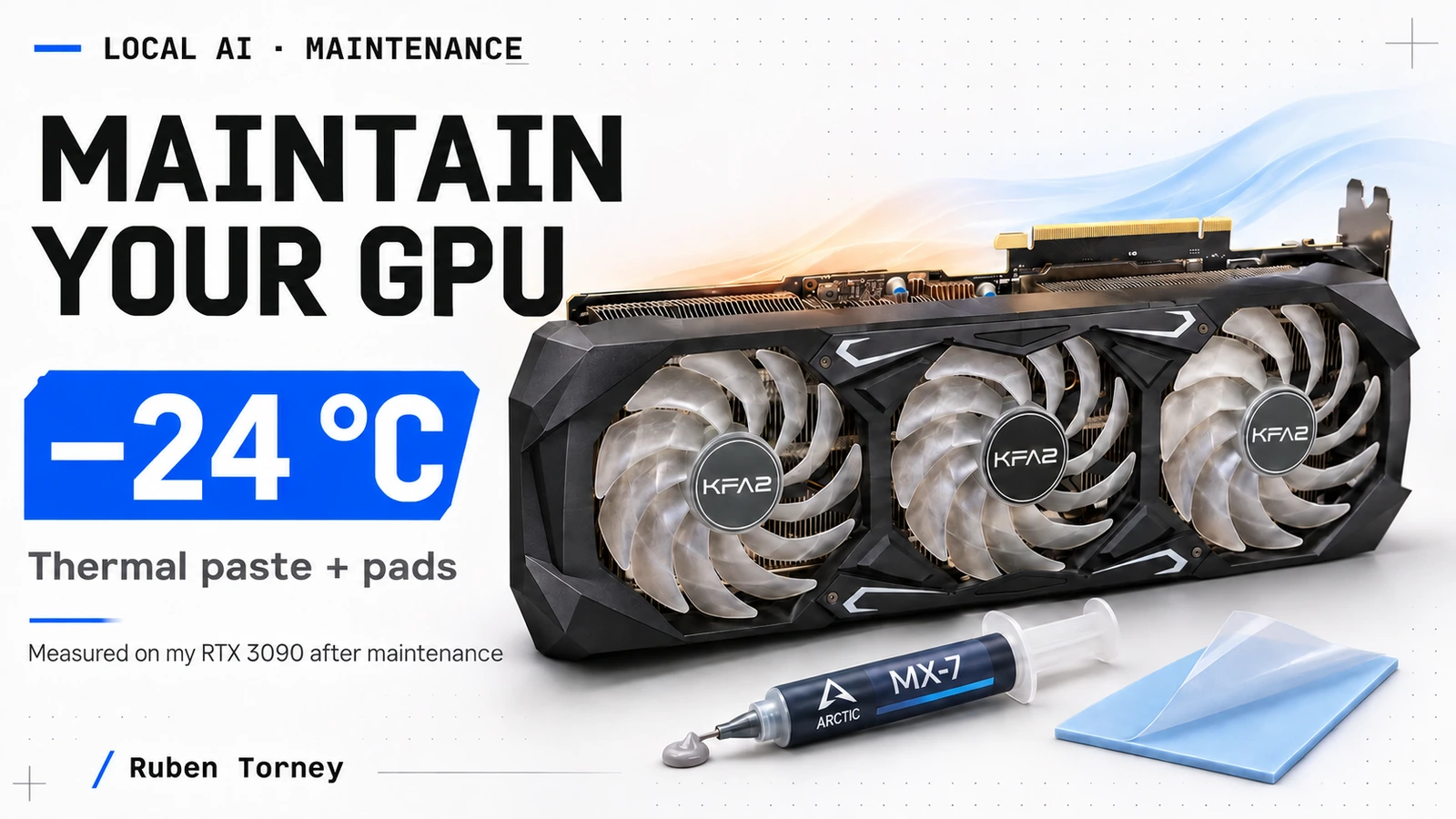
How NVIDIA, AMD and Intel graphics cards are cooled
Whether you use an NVIDIA GeForce, AMD Radeon or Intel Arc, air cooling follows the same principle, moving heat from the components to a heatsink and then into the air. My walkthrough uses a KFA2 RTX 3090 as the example; check interface locations and thicknesses against the instructions for your exact model.
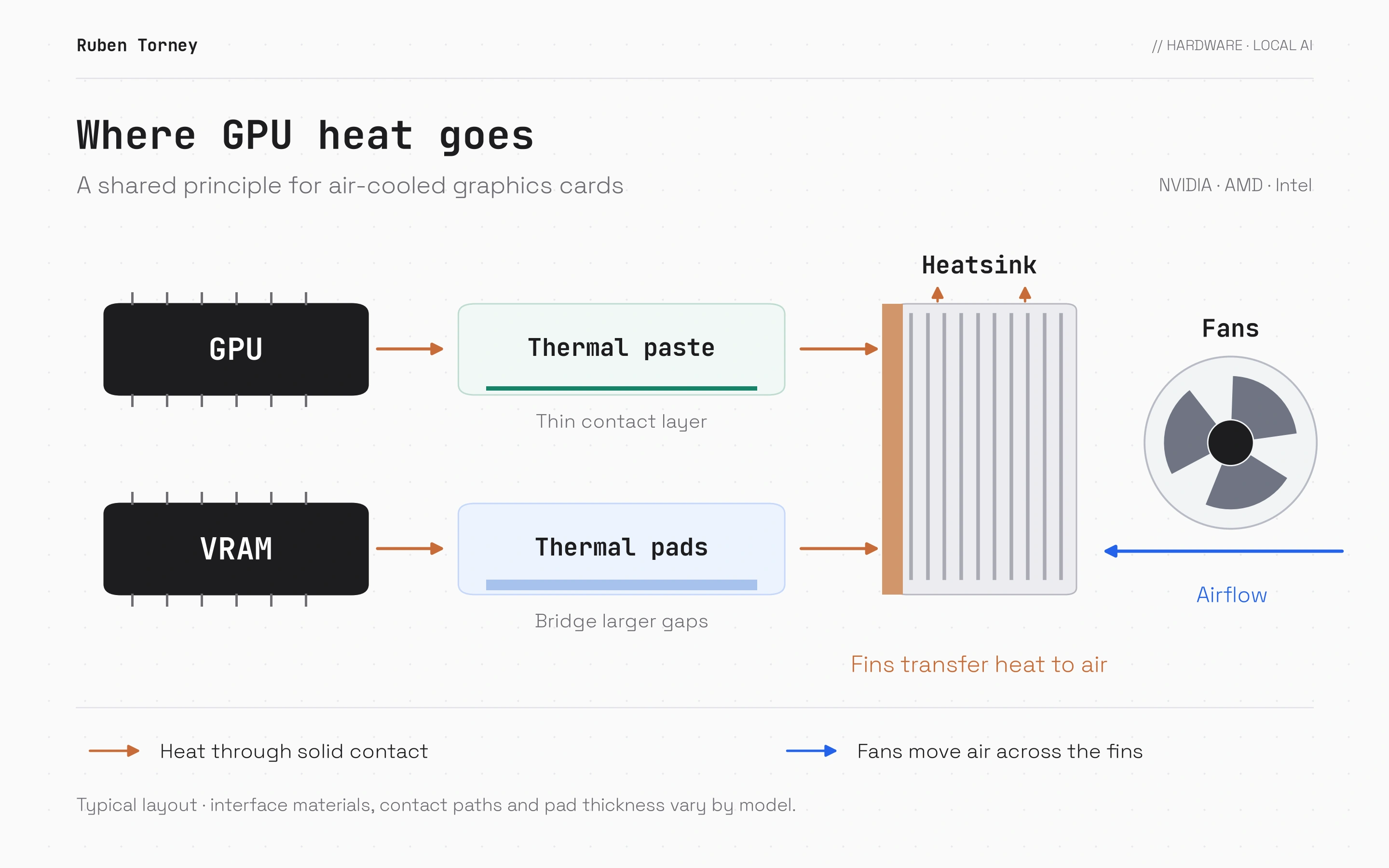
- GPU → thermal paste → heatsink. Paste fills microscopic surface irregularities between the graphics chip and its contact surface to help heat transfer.
- VRAM → thermal pads → heatsink or backplate. Pads bridge gaps between memory chips and their cooling surface. Correct thickness and contact are essential.
- Heatsink → air. Fins provide a large heat-exchange surface. Fans circulate air to carry the heat away.
Some cards use other interfaces, such as phase-change material or thermal putty. Follow the assembly specified by the manufacturer. ARCTIC explains the role of paste and pads in these thermal contacts.
Cooling matters for local AI and AI agents running repeated tasks. A card reducing its clocks under heat can take longer to generate responses and complete tool loops. Maintenance aims to keep performance consistent during generation and repeated tasks.
We spend plenty of time discussing models, quantization and inference engines, the software that runs those models. At the end of that chain sits a graphics card doing the work, generating heat and getting older. Sometimes optimization starts with cleaning, thermal paste and pads that make proper contact.
My card is about six years old. During earlier use, I had seen it enter a protection state and noticed throughput declining on long sessions. Its paste may not have been replaced since it was new. I decided to revisit the cooling and measure what changed on my local AI workload.
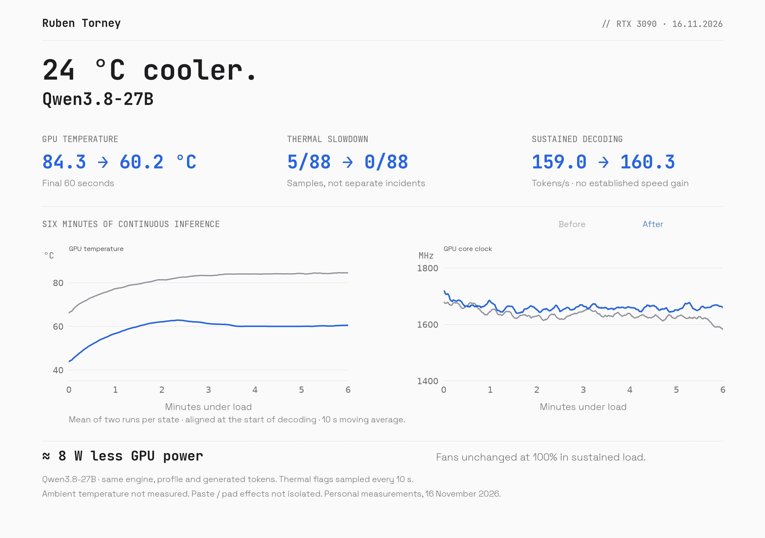
The result, 24 °C cooler with throughput preserved
| Plateau measurement | Before, mean of two runs | After correction, mean of two runs |
|---|---|---|
| GPU core temperature | 84.3 °C | 60.2 °C |
| Sustained decoding | 159.0 tokens/s | 160.3 tokens/s |
| GPU core clock | 1,616 MHz | 1,662 MHz |
| Reported GPU power | 345.6 W | 337.6 W |
| Fans | 100% | 100% |
| Readings with thermal slowdown, across complete runs | 5 / 88 | 0 / 88 |
Twenty-four degrees is a huge change on this card. I keep roughly 160 tokens/s with a much cooler GPU. That is the main benefit of this maintenance.
Extended sessions, a maximum of 75 °C
On November 16, I extended the tests with long contexts on Qwen3.8-27B. The result was a maximum of 72 °C during a 17.6-minute session and 75 °C during a 26.2-minute session, with no recorded thermal throttling.
| Session after maintenance | Prompt context | Total duration | Maximum GPU core temperature | Thermal slowdown readings |
|---|---|---|---|---|
| First session | 131,072 tokens | 17.6 min | 72 °C | 0 / 105 |
| Second session | 244,000 tokens | 26.2 min | 75 °C | 0 / 156 |
Durations include long-prompt prefill, decoding and idle phases. These sessions use a quantized memory-cache profile suited to long contexts. The extended-session measurement summary is available here.
A peak of 75 °C is a very good result under this workload. For reference, NVIDIA lists a maximum GPU temperature of 93 °C for the RTX 3090 Founders Edition. My maximum is 18 °C below that reference value. There is comfortable thermal headroom, and cooling holds up during these extended sessions too.
How I compared the runs
The machine has a 24 GiB RTX 3090 capped at 350 W, a Ryzen 5 5600X and 125 GiB of RAM. The model is Qwen3.8-27B, in a quantized version, with the same engine and profile before and after. This follows my experience with open-weight models and local AI.
Each run includes idle and warm-up phases, then six minutes of continuous decoding, using requests that generate 512 tokens. There are two runs before and two after the corrected reassembly. Results compare the means of their final 60 seconds.
The binary, arguments and generated-token hashes match. Temperatures and clocks are sampled at 1 Hz; slowdown reasons are checked every ten seconds. The measurements and calculation method are available here.
The results cover the complete intervention, including paste and pad replacement and corrected contact.
Replacing the pads and thermal paste, step by step
The principle applies to maintaining other air-cooled cards, following their own instructions. Here is how I worked on my KFA2 RTX 3090, with the photographs in order. Before opening it, I shut down the PC, unplug the power and remove the card. I use a suitable work surface and take precautions against static electricity. I photograph the pads and record each screw's position before removal, since screw lengths and locations can differ.
Allow roughly one to two hours for this job. The time depends on your experience and how carefully you work through screw identification, cleaning and reassembly. Set aside around two hours to work at a comfortable pace.
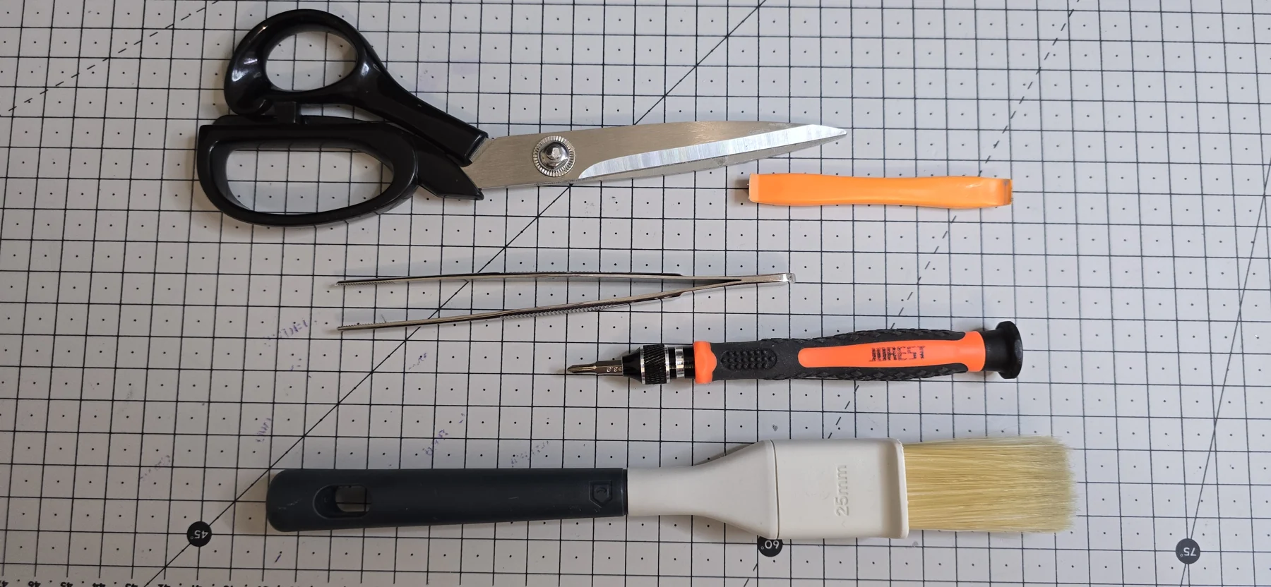
0. Prepare the tools
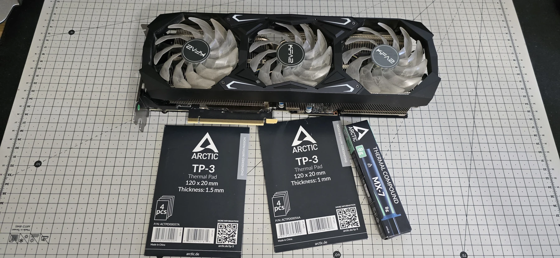
My tools are scissors for cutting pads, a small plastic spudger to help lift without levering against components, tweezers for removing protective film, a suitable Phillips screwdriver and a soft electronics-safe brush for dust and loose residue. I also need soft lint-free wipes, or suitable paper, and isopropyl alcohol for cleaning the interfaces. There is no need to scrape components with a metal tool.
1. Locate the backplate screws
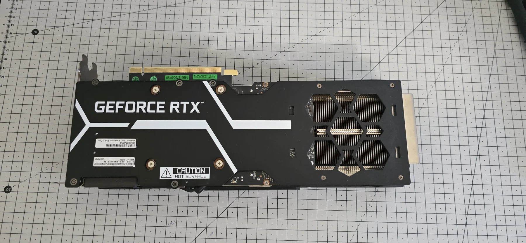
I start on the rear side. Pay attention to screw locations: lengths vary, and my card has different screw counts on each side. I mark every position on a photograph or diagram and sort the screws in assembly order. Each screw must return to its original location.
The wrong screw length can prevent the backplate or heatsink from seating properly, or even damage the card. Pads may then make poor contact with the VRAM, reducing heat transfer and potentially causing thermal throttling. A few minutes spent organizing screws can save another teardown.
2. Remove the backplate and remember the rear VRAM
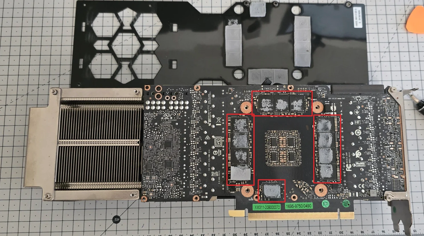
With the plate removed, the old pads and twelve rear VRAM modules on this card become visible. These memory chips need cooling too. Their pads deserve attention even though they sit under the backplate. I photograph their positions before cleaning.
3. Separate the three assemblies
For this job, I stop at three assemblies, the heatsink with its fans, the PCB carrying the GPU, and the backplate. PCB means the card's printed circuit board. I watch the fan and lighting cables and connectors while separating the parts so I do not pull on them.
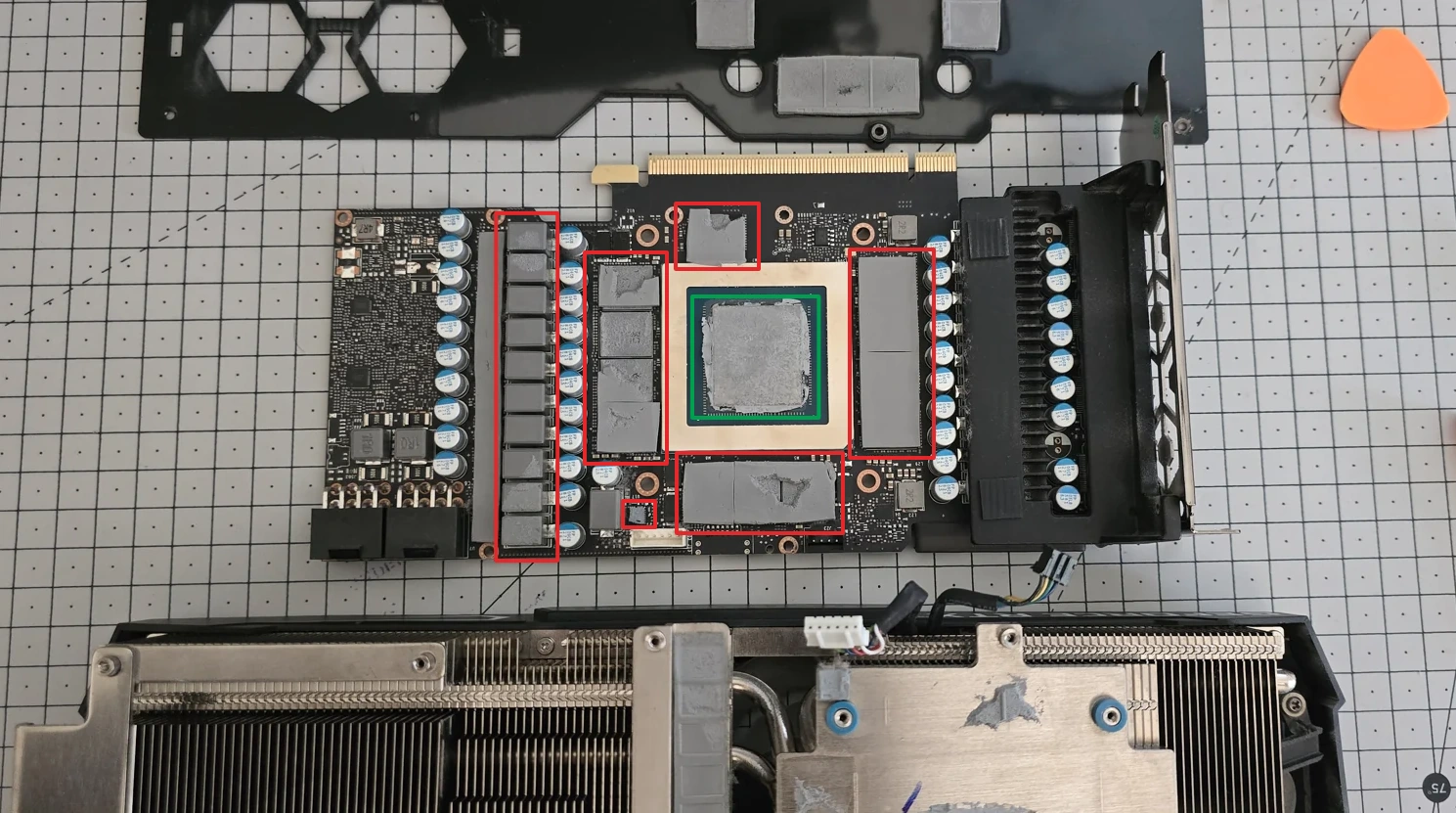
Old paste can hold the GPU firmly against the heatsink. Once all relevant fasteners are removed, I use very gentle, tiny oscillations parallel to the contact surfaces to release that adhesion gradually. I do not pull sharply, bend the PCB or lever against the die. If it resists, I check the screws and cables again before continuing.
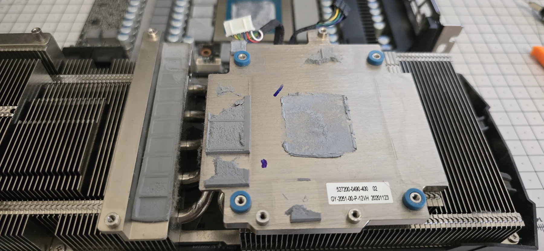
The photograph still shows paste, but it is old. I replace it after opening, along with the pads.
4. Clean both sides and the heatsink
4.0. Before cleaning. Old pads have left residue on the chips and old paste remains on the GPU. I gently remove the worn interfaces without pulling off nearby small components.
This is where the small plastic spudger comes in handy. It helps gently lift and peel old pads away from the components. I work slowly, without pressing on the small components underneath or using them as a fulcrum.
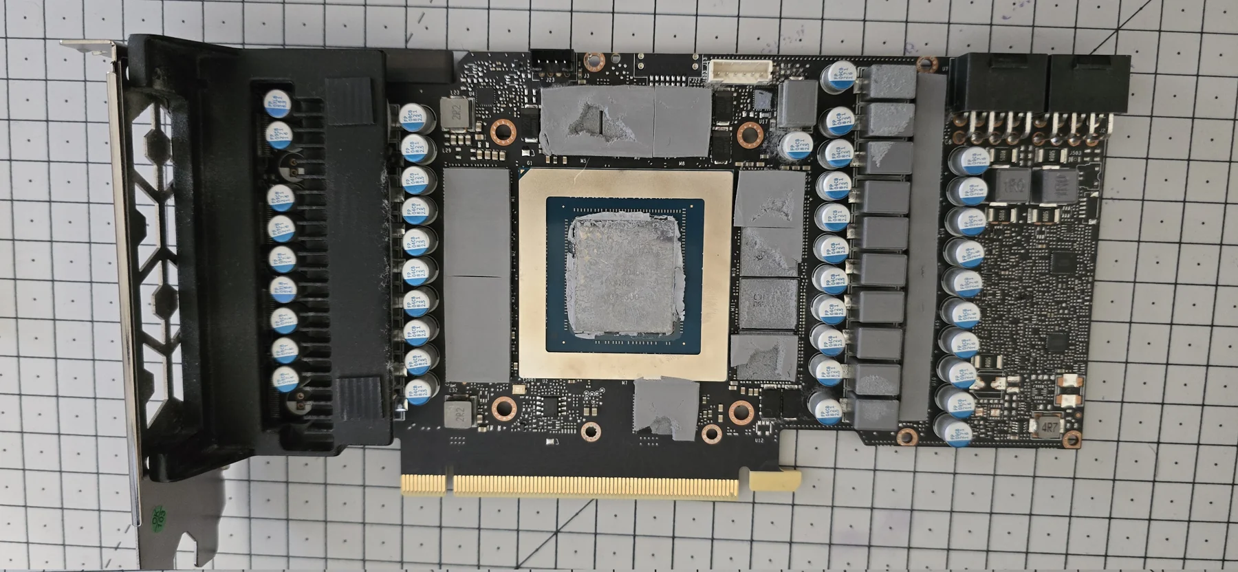
4.1. GPU side. I clean in small passes with a lint-free wipe lightly moistened with isopropyl alcohol. I regularly use a fresh section to absorb residue rather than spread it around. The brush helps remove loose debris, not scrape components. Everything must dry completely before new interfaces go on.
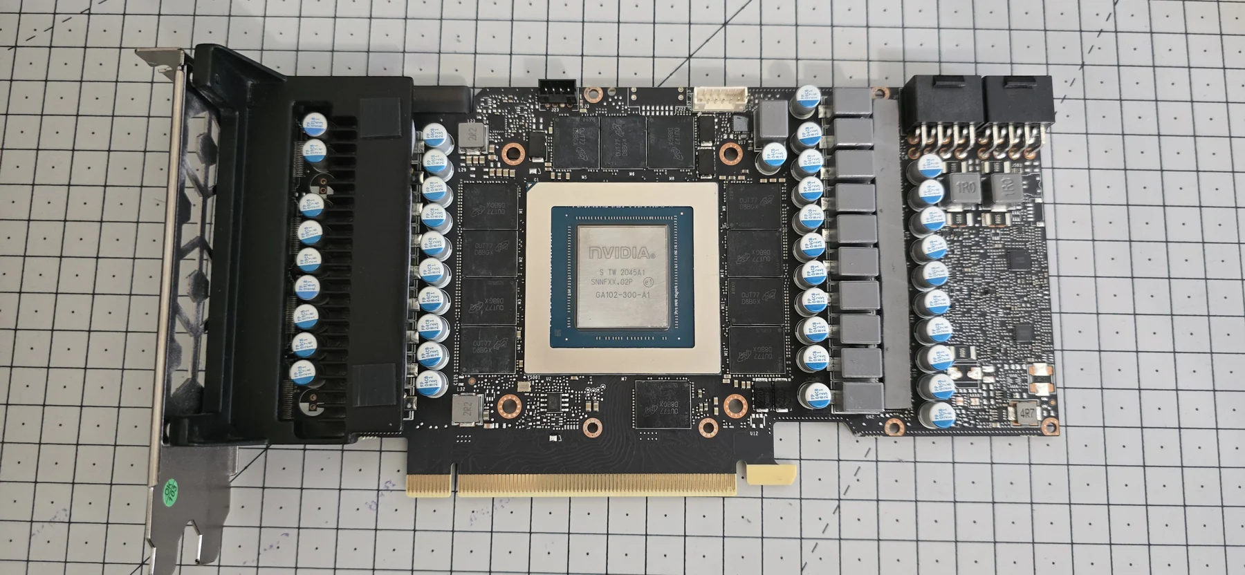
4.2. Rear side. I repeat the process on the rear VRAM, removing old pad fragments to leave clean contact surfaces.
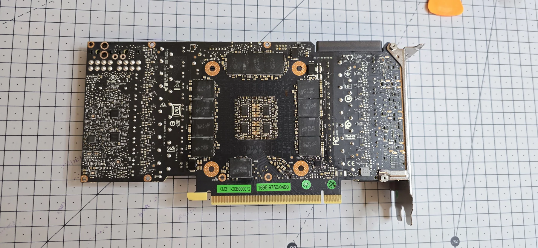
4.3. All parts. I also clean the heatsink and backplate contact surfaces. The aim is to remove old interface residue while retaining the insulation and other parts of the original assembly. ARCTIC also describes cleaning and protective film removal in its pad instructions.
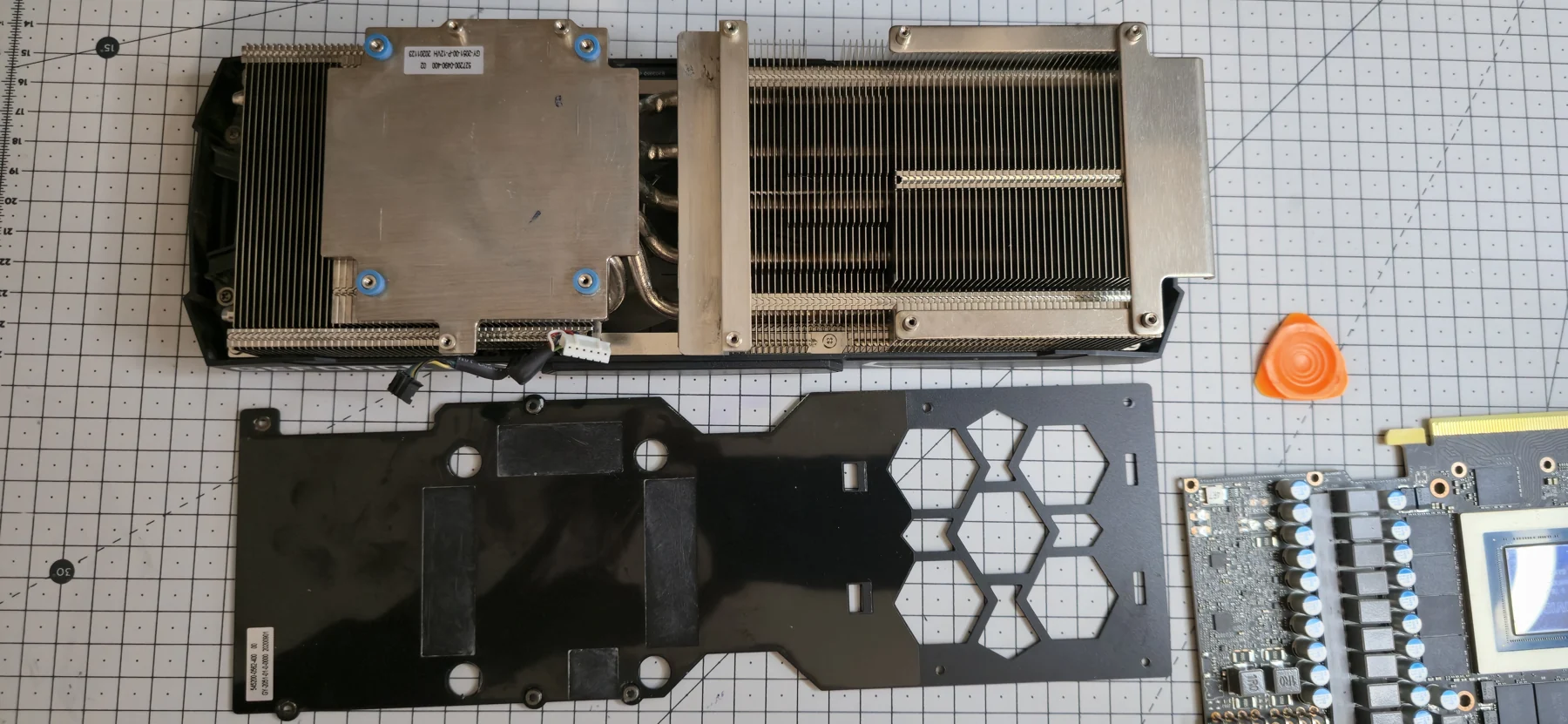
5. Cut the pads and apply paste
I use ARCTIC pads and paste here. Thickness is essential. For my KFA2 assembly, the thicknesses I report are 1.5 mm on the heatsink side and 2 mm under the backplate. These dimensions apply to my assembly. For your card, check the layout for the exact model and revision, each location and the pad specifications.
A pad that is too thin may leave a gap; one that is too thick may prevent the heatsink from seating correctly on the GPU. Softness and compression matter too, as ARCTIC explains in its thermal pad guidance. The goal is correct contact, rather than maximum thickness.
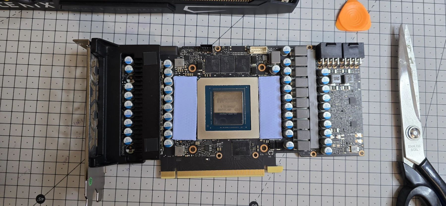
I cut the pads with scissors away from the card, covering the intended surfaces as evenly as possible. Any small overhang must not interfere with nearby components or fasteners. I refer to the original photograph so I do not miss a location, including the pad strip on the heatsink. Before closing, I check that all required protective films have been removed from both pad faces, using tweezers if needed.
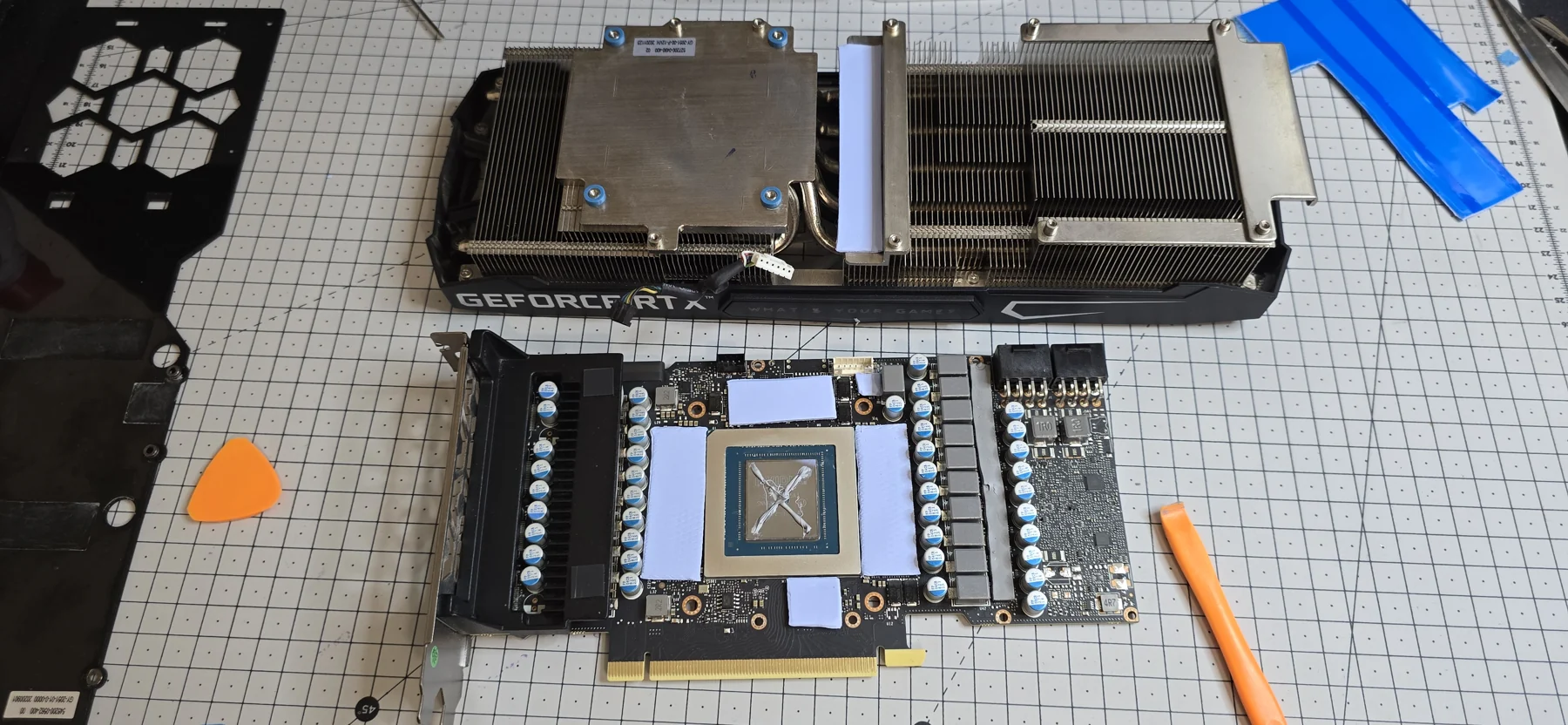
The photograph shows my cross pattern on the GPU. That is the method used with this paste in my test. On a bare die, the essential requirement is complete, even coverage of the contact surface, using an appropriate amount and following the product instructions. Paste goes on the GPU; pads bridge the other intended contact areas.
6. Refit the heatsink and tighten gradually
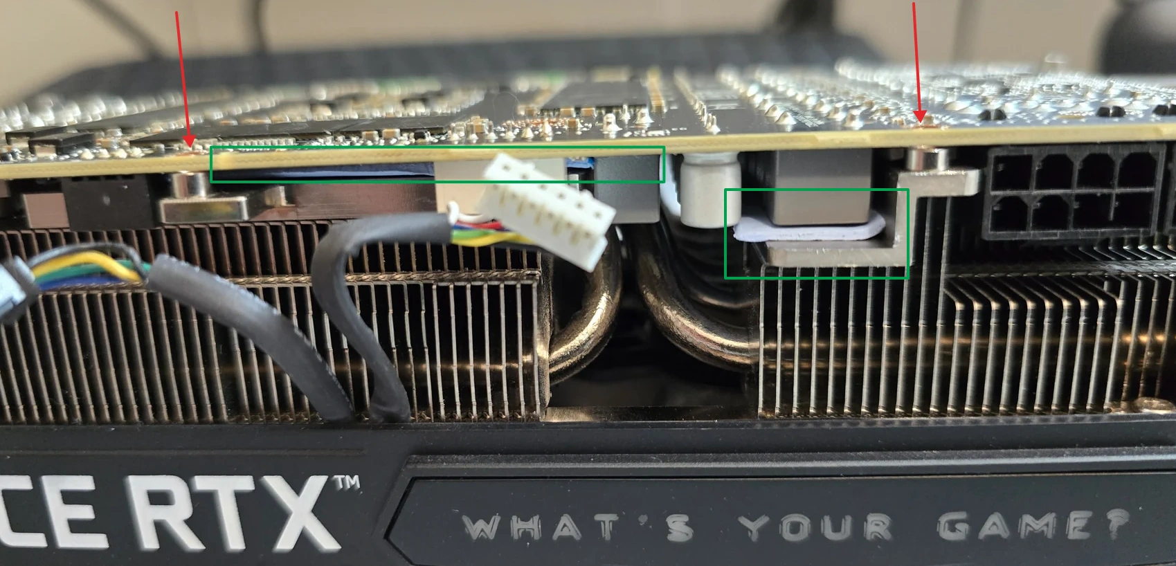
6.0. Lower straight down. With paste and pads in place, I align the PCB above the heatsink. I check the cable routing and lower it straight down, without displacing pads or rotating the parts against each other. The tiny oscillations were for disassembly, not this stage.
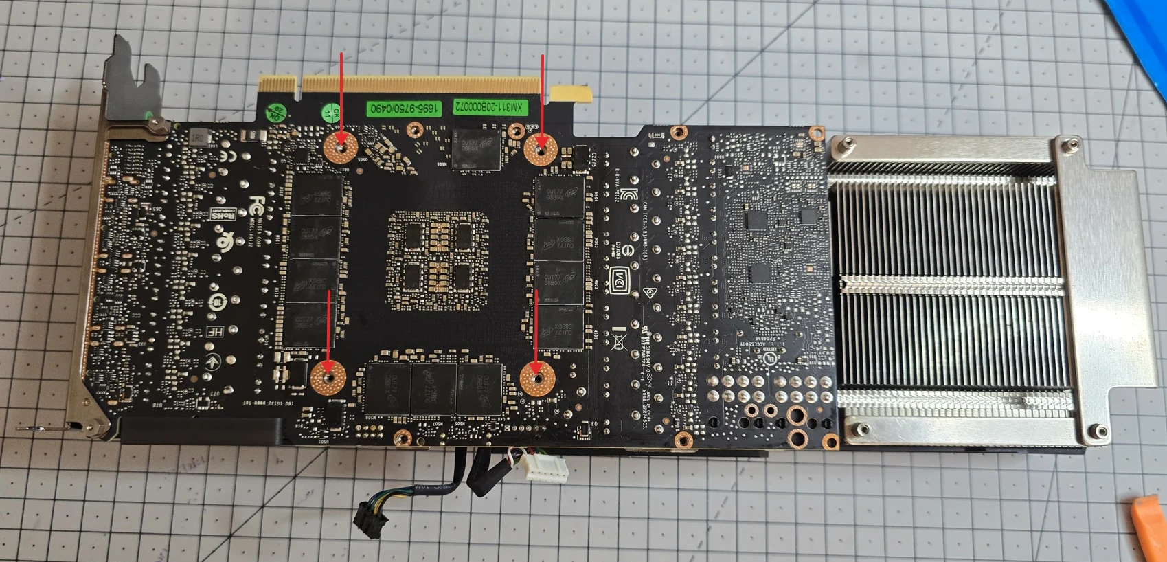
6.1. Align the fasteners. I check the holes before engaging screws. A screw should not be used to force misaligned parts together.
6.2. Tighten diagonally. I lightly engage all four screws around the GPU, then tighten progressively in a cross pattern, alternating diagonals. At first, I use one or two small turns at a time, rather than tightening one screw fully while the others remain loose. I respect the stops and manufacturer tightening instructions without forcing anything.
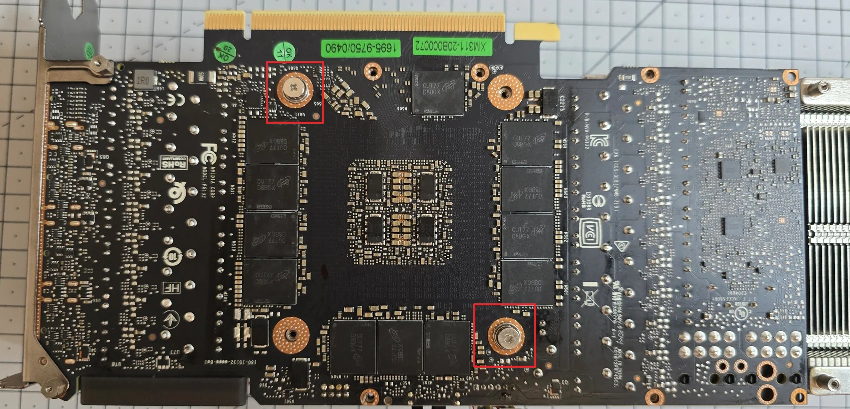
6.3. All four screws are fitted. The GPU is now secured to the heatsink. Even tightening balances pressure and helps distribute paste across the die. Maximum tightening force is not the objective.
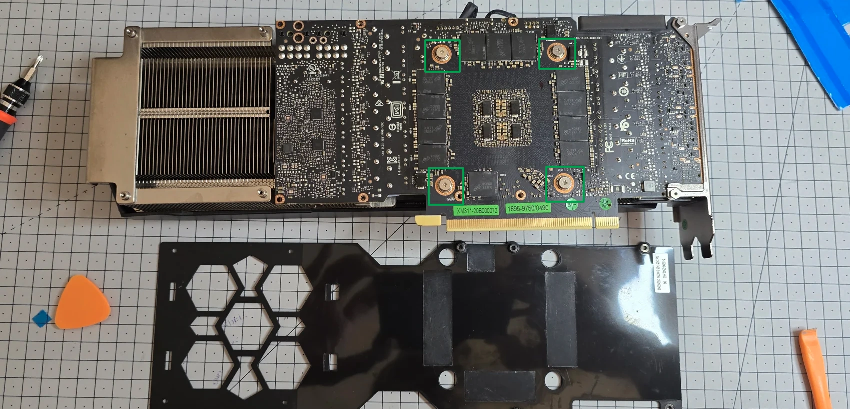
6.4. Fit the backplate pads
I replace the rear pads at the locations recorded before disassembly. Their thickness and contact with the VRAM are critical. On my assembly, this is the side where I report 2 mm. I check coverage, film removal and positioning before closing. The backplate needs to receive heat from the memory, rather than simply cover the rear of the card.
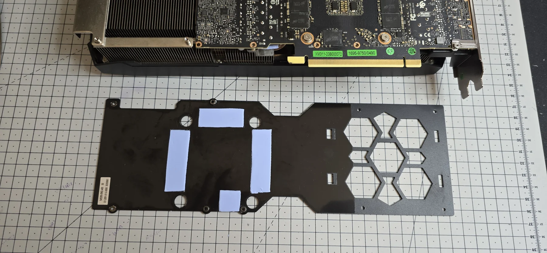
7. Complete the assembly
I refit the backplate to the PCB and heatsink assembly and return each screw to its original location. I first engage every screw's thread without fully tightening it. Then I tighten gradually, alternating opposite sides, for example one or two small turns on one screw followed by the same on the opposite screw. This progressively distributes pressure between the backplate, PCB and heatsink without bending the board. I tighten without forcing, following the manufacturer's instructions. I check fan connections and cable routing before reinstalling the card. Load measurements come next, to check that cooling works across the card.
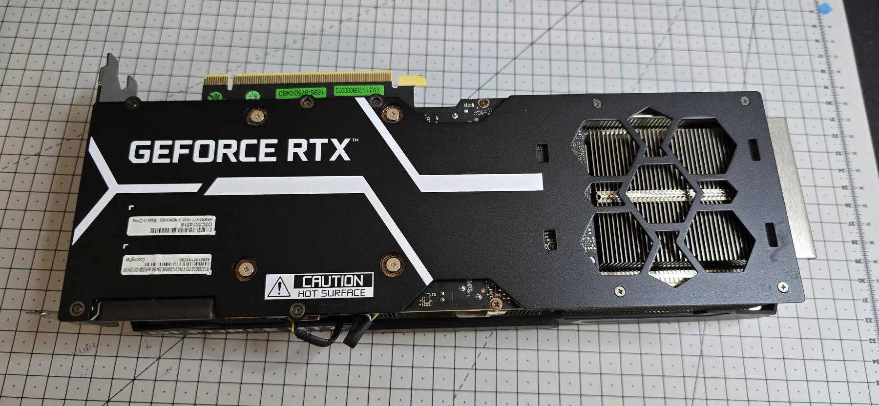
The mistake I encountered on the first reassembly
The first reassembly went badly. The GPU core looked well cooled at 48.9 °C on the plateau, but throughput fell to 126.2 tokens/s, around 21% below the original baseline. The driver reported thermal slowdown in 29 of 46 readings.
When reopening the card, I found a gap between the thermal pads on the rear VRAM and the backplate, the rear metal plate that helps passively dissipate its heat. The pads were too thin to make contact. I doubled their thickness by stacking them to fill that gap and restore contact with the backplate. This means thermal pads, rather than a thicker layer of thermal paste.
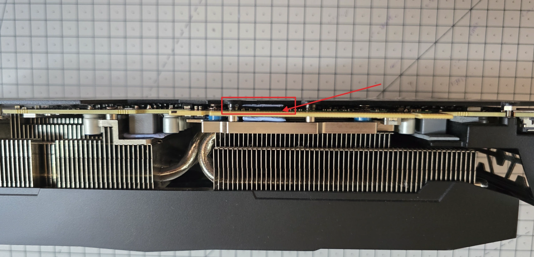
After this second reassembly, expected throughput returned and neither of the two runs recorded thermal slowdown. The overall maintenance result is the one shown above, with the GPU core running about 24 °C cooler. Required pad thickness depends on the card and actual contact, so doubling pads is not a universal procedure.
This detour shows that the backplate matters too, particularly with VRAM on the rear of the card. Cooling the GPU core well is not enough if memory cannot shed its heat properly. Rear pad contact with the backplate deserves as much attention as paste on the GPU.
Five thermal slowdown readings before, none after
The two original runs contain 2 and 3 active SW Thermal Slowdown readings, out of 44 checks each. After correction, both runs contain 0 out of 44. That gives 5/88 before and 0/88 after.
These checks, taken every ten seconds, show thermal throttling before maintenance and none after correction.
After maintenance, the card remains within its 350 W power envelope, reported through SW Power Cap. NVIDIA documents these different clock-reduction reasons.
The core clock rises by roughly 2.8%, memory clock stays unchanged and throughput remains around 160 tokens/s. The benefit is keeping expected performance with more thermal headroom.
Cooling also affects the cost of running AI
This is where the subject connects with FinOps, managing technology costs and the value they deliver. Hardware, energy and useful performance belong in the same calculation. A cheaper card that repeatedly enters protection does not necessarily offer a lower cost per task. This complements my discussion of AI agent costs.
Reported GPU power falls by roughly 8 W, or 2.3%, at similar throughput. On one card, that is a modest saving. If the difference persisted over 1,000 hours, it would amount to about 8 kWh. At a purely illustrative €0.25/kWh, that is €2. This is an order of magnitude based on reported GPU power.
Data centres also pay to remove heat. The International Energy Agency estimates that cooling and environmental controls account for roughly 7% of electricity consumption in efficient hyperscale sites and over 30% in some less-efficient enterprise sites.
I see cooling as a practical operations and FinOps lever, alongside utilization, model choice and architecture. Maintaining performance, avoiding interruptions and keeping hardware usable for longer have value. In my view, maintenance, thermal monitoring and cooling skills will matter increasingly as AI expands. This connects with the efficiency trade-offs discussed by the FinOps Foundation.
What I will watch next
The goal is hardware that works reliably over time. I continue tracking temperatures, clocks, slowdown reasons and tokens/s during local AI workloads.
This thermal headroom also gives room to adjust fan settings and seek better acoustic comfort. In the six-minute comparison shown here, fans remain at 100% at the plateau.
I also want to keep using this hardware rather than replacing it early. Regular maintenance starts with monitoring, cleaning and intervening when symptoms justify it, rather than routinely dismantling a healthy card. Disconnecting power, taking electrostatic precautions and documenting the assembly matter before opening it; when unsure, I would use someone familiar with the card.
My overall view is very positive. I gain about 24 °C of thermal headroom and keep my local AI throughput with a few watts less GPU power. The extended sessions also show controlled temperatures. I will continue monitoring the assembly over time. When hardware is an investment in generating tokens, cooling deserves attention too.
Sources and measurements
-
Personal run results, curves and method from November 16, 2026. Two original runs, two corrected runs and the unsuccessful first reassembly retained.
-
NVIDIA, nvidia-smi documentation, checked November 16, 2026. Sensors and clock-reduction reasons.
-
IEA, Energy and AI, Energy demand from AI, 2025 report, checked November 16, 2026. Data-centre cooling.
-
FinOps Foundation, Sustainability, checked November 16, 2026. Efficiency, financial value and environmental trade-offs.
-
Personal photographs by Ruben Torney, taken November 16, 2026 during the intervention.
-
ARCTIC TP-4 instructions and thermal pad selection guidance, accessed November 17, 2026. Cleaning, protective films, thickness and compression. These general references are not a KFA2 pad layout.
-
Personal extended-session measurements from November 16, 2026, maximum temperatures and thermal slowdown readings.
-
NVIDIA RTX 3090 Founders Edition specifications, accessed November 17, 2026. Reference maximum GPU temperature, 93 °C.